Stabilization theory and functionality
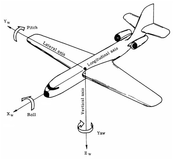
The quadcopter can be developed using one of the 2 configurations below. In our case, the plus configuration was done and all the control system was based on it. The quadcopter has 3 axis: pitch, roll and yaw. These 3 angles determine orientation and thereby the direction of the quadcopter. That means, changing the pitch will make the quadcopter go forward or backward, the roll provides movement to the left or right, and finally the yaw will make it rotate around its vertical axis. The control routine follow a very simple basis and it will be explained next.
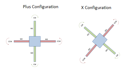
The idea is to change each motors speed to compensate the movement to a stable state of the device. Supposing the desired movement is forward or backward. This is caused by pitch angle and it is necessary to change the speed of the two motors on the Y axis.
This can be achieved by giving more power to one and less to another based on gyros reading to compensate the difference of angle. If the quad had a forward movement (differentiation), motor 1 has to receive more power to go up and motor 4, less power to go down (following the scheme in the figure above). Case backward, more power to motor 4 and less to motor 1.
Similarly, the roll angle works the same for left and right but controlling motors 2 and 3. Finally, the yaw angle. As each rotor produces thrust and torque about its center of rotation when pairs of motors are rotating, the yaw is induced by the difference in torque. So, the value has to be set by offsetting the speed between the counter-rotating propeller pairs.
In our case M5 is our 3rd motor and M6, the 4th. Right below you can see the code for stabilization. This theory was followed in addition to a calibration of our gyros responses to make sure the output was consistent.
M1 +=  -Pitch  -  Yaw;
M2 +=  -Roll   +  Yaw;
M5 +=   Roll   -  Yaw;
M6 +=   Pitch  +  Yaw;
The stabilization routine is based on reading AD Conversion, applying a gain and defining a sensibility for these values.
void Stabilize()
//Stabilizes the quad by sampling adc and adjusting motors accordingly
{
    int Yaw   = 0;
    int Pitch = 0;
    int Roll  = 0;
    float kp	= 1.0/8.0;
    float tmp = 0;

    //********Read Yaw*********************************************
    Yaw  = ADCsingleREAD(YAW);
    // ADCvalue now contains an 10bit ADC read
    Yaw -= YawInit;  //Subtract from default reading value
    tmp = Yaw * kp;
    Yaw = (int)tmp;

    //********Read Pitch*******************************************
    Pitch  = ADCsingleREAD(PITCH);
    // ADCvalue now contains an 10bit ADC read
    Pitch -= PitchInit;
    tmp = Pitch * kp;
    Pitch = (int)tmp;

    //********Read Roll********************************************
    Roll  = ADCsingleREAD(ROLL);
    // ADCvalue now contains an 10bit ADC read
    Roll -= RollInit;
    tmp = Roll * kp;
    Roll = (int)tmp;

    //High Pass Filter
    if(Yaw   >= -1 && Yaw   <= 1) Yaw   = 0;
    if(Pitch >= -1 && Pitch <= 1) Pitch = 0;
    if(Roll  >= -1 && Roll  <= 1) Roll  = 0;

    tempM1 += -Pitch - Yaw;
    tempM2 +=  -Roll + Yaw;
    tempM5 +=  Roll  - Yaw;
    tempM6 +=  Pitch + Yaw;

}